Reworked Night vision on ESP32-CAM

Original credit and KUDOS to Hackermagnet at https://hackermagnet.com/night-vision-on-esp32-cam/ for the original STLs and working this out in the first place. He (hope I am using the correct pronoun) has some cool projects so be sure to check out the website.
ESP projects are fascinating to me and can usually be built relatively low-cost. My home is already surrounded by cameras but there is always room for more. In-fact, having just set-up Home Assistant in our camper, this project was a timely find to give it a little surveillance as well. In addition, this device integrates via ESPHome to make programming super easy.
When I initially went to build the Night vision on ESP32-CAM project, I ran into a few issues. Some of these were questions that later had answers and some did not. During initial assembly, things did not fit together as I had hoped. The IR LED ring did not set in (was later told I was suppose to break off the posts), the HR-SC501 did not fit into it's place (might have it I took off the headers), and the cap would not fit (would have if I had removed the ESP32-CAM headers). When I wired things up based on the drawing, there would be a clicking and everything would shut-off. This may have been due to different parts used or taking the wiring diagram too literally.
Another point, Hackermagnet obviously had a specific use for this project but after assembling two, it occurred to me that a more automatic functionality could probably be obtained but just plugging the M12 IR cut filter directly into the IR LED board and bypassing the MX1508 altogether. Hackermagnet's version (same as below) will require either manual switching or an automation to trigger the IR Filter on and off.
Parts required:
- ESP32CAM module w/antenna - Amazon or AliExpress
- MP1584EN DC to DC Buck - Amazon or AliExpress
- M12 3MP lens (no IR) - Amazon or AliExpress
- M12 IR cut filter, holes distance 20mm - Amazon or AliExpress
- IR LED board 12V 45mm - AliExpress
- MX1508 H-bridge module - Amazon or AliExpress
- HC-SR501 PIR module - Amazon or AliExpress
- DHT22 Temp/Humidity sensor - Amazon or AliExpress
- Dupont or similar jumper wires
- JST-PH2.0 2-pin wire - Amazon or AliExpress
- Soldering iron and accessories
- X2 M2x16 (for retracted) or X2 M2x12 (for extended) countersunk self tapping screws
- X3 M2x6 countersunk self tapping screws
- X4 M3x8 pan head machine screws with hex nuts
- Hot Glue Gun or 3D pen
- 3D printer and these files: Thingiverse or at end of post.
Wiring Schematic:
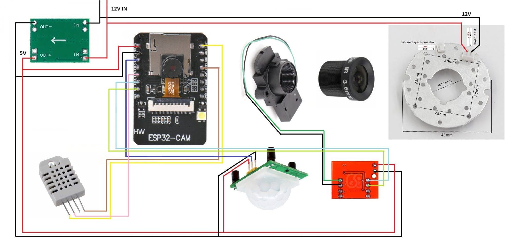
Things to note when wiring:
- Always check the pinouts and polarity. My JST connectors needed to be reversed for the IR LED board.
- The IR LED board requires 12V but everything else needs 5V (hence the MP1584EN DC to DC Buck).
- Be sure to check the MP1584EN DC to DC Buck is converting from 12V to 5V. Especially if you get the adjustable ones like I did. Mine were set closer to 10V output.
- Antenna tutorials: here or here
- Some parts will need to be soldered but more can be connected with the Dupont connectors if you choose to do so.
- A 12V power source is needed. 500MA or 1A should be sufficient to power the entire camera and components. I did not detail this part but it will need to connect to the IN of the MP1584EN.
Code: (Pretty much a direct copy from Hackermagnet's blog)
I recommend uploading the code before wiring everything up. Even if you leave the headers on as I did, this will still make it easier to test along the way.
substitutions:
  devicename: esp-cam
  friendlyname: ESPcam

esphome:
  name: $devicename
  platform: ESP32
  board: esp32cam

wifi:
  ssid: !secret wifi_ssid
  password: !secret wifi_password
  fast_connect: on
  ap:
    ssid: $friendlyname Hotspot
    password: !secret ap_password

captive_portal:

logger:

api:

ota:

sensor:
  - platform: dht
    pin: 15
    temperature:
      name: $friendlyname Temperature
      filters:
        - offset: -0.5 #adjust as necessary to correct reading
        - sliding_window_moving_average:
            window_size: 15
            send_every: 15
    humidity:
      name: $friendlyname Humidity
      filters:
        - offset: 2.5 #adjust as necessary to correct reading
        - sliding_window_moving_average:
            window_size: 15
            send_every: 15
    update_interval: 15s
    model: AM2302

binary_sensor:
  - platform: gpio
    pin: GPIO12
    name: $friendlyname Motion Sensor
    device_class: motion
  - platform: homeassistant
    name: "Input Boolean Night Mode HA"
    entity_id: input_boolean.esp32_night_mode
    on_press:
      then:
        - switch.turn_on: ir2
    on_release:
      then:
        - switch.turn_on: ir1

esp32_camera:
  external_clock:
    pin: GPIO0
    frequency: 20MHz
  i2c_pins:
    sda: GPIO26
    scl: GPIO27
  data_pins: [GPIO5, GPIO18, GPIO19, GPIO21, GPIO36, GPIO39, GPIO34, GPIO35]
  vsync_pin: GPIO25
  href_pin: GPIO23
  pixel_clock_pin: GPIO22
  power_down_pin: GPIO32

  name: $friendlyname Door Camera
  resolution: 640x480
  jpeg_quality: 20 #10 best, 63 worst
  idle_framerate: 0.4 fps
  max_framerate: 5 fps
  vertical_flip: true
  horizontal_mirror: true

switch:
  - platform: gpio
    pin: GPIO2
    name: $friendlyname IR ON
    id: ir1
    on_turn_on:
    - delay: 100ms
    - switch.turn_off: ir1
    interlock: [ir2]
  - platform: gpio
    pin: GPIO14
    name: $friendlyname IR OFF
    id: ir2
    on_turn_on:
    - delay: 100ms
    - switch.turn_off: ir2
    interlock: [ir1]
Assembly:
Gather all your components and 3D printed parts. I soldered and wired everything up pre-assembly but do whatever works best for you. The only note I have regarding the prints is the little square within ESP32CAM_IR_sensor_holder_V2 (applies to both extended and retracted). You may need to file or sand it GENTLY to ensure the OV2640 camera will fit in. It's okay to be snug but you will need it to fit flush.
Speaking of the OV2640 camera, you will need to remove the lens. These are glued on and can be a little difficult to remove. I gently cut the glued area with a Xacto-knife and then used two pairs of piers to gently break it free and then unscrewed the rest of the way by hand. Once you get it apart, keep or discard the lense as you will be replacing it with the M12 3MP lens. Set the camera base with the ribbon cable aside for now.
There are two versions of ESP32CAM_IR_sensor_holder_V2. Which one you use determines how far the camera lens will ultimately extend from the front of the camera body. Use the extended for it to be out further or the retracted for it to be more flush.
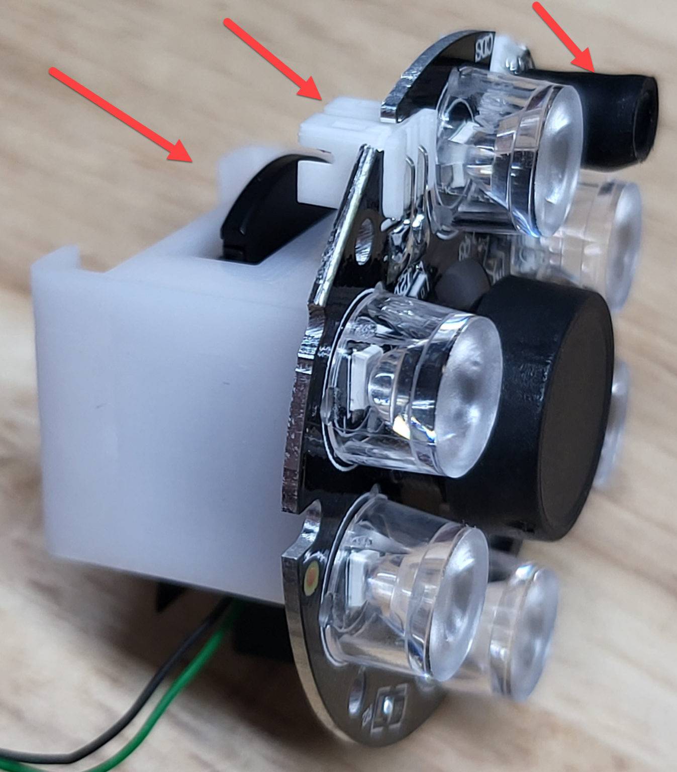
Screw the M12 3MP lens into the M12 IR cut filter. Then slide the M12 IR cut filter to the ESP32CAM_IR_sensor_holder_V2 as shown below. Be sure to note the direction of placement.
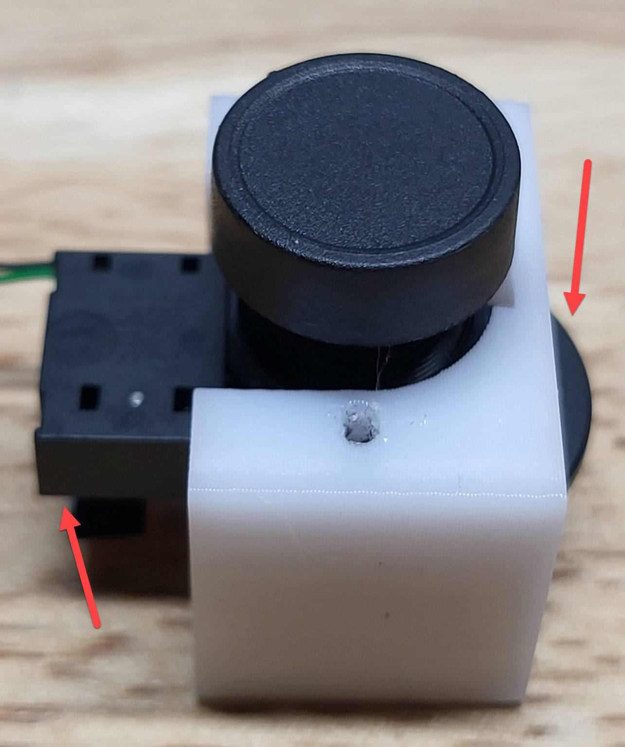
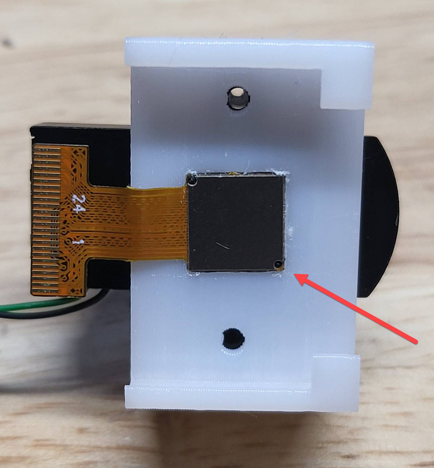
Now take the OV2640 camera and gently insert into the square hole of the ESP32CAM_IR_sensor_holder_V2 which goes a little inside the M12 IR cut filter. Again, note the direction of placement.
Now take the IR LED board and place over the lens. Mount it in place with 2 M2x16 (or M2x12 depending on version of holder) countersunk self tapping screws. The board should snug up tightly and be sturdy but be careful not to over-tighten and strip the holes. Once again, pay attention to the placement as it will affect the mounting into the case.
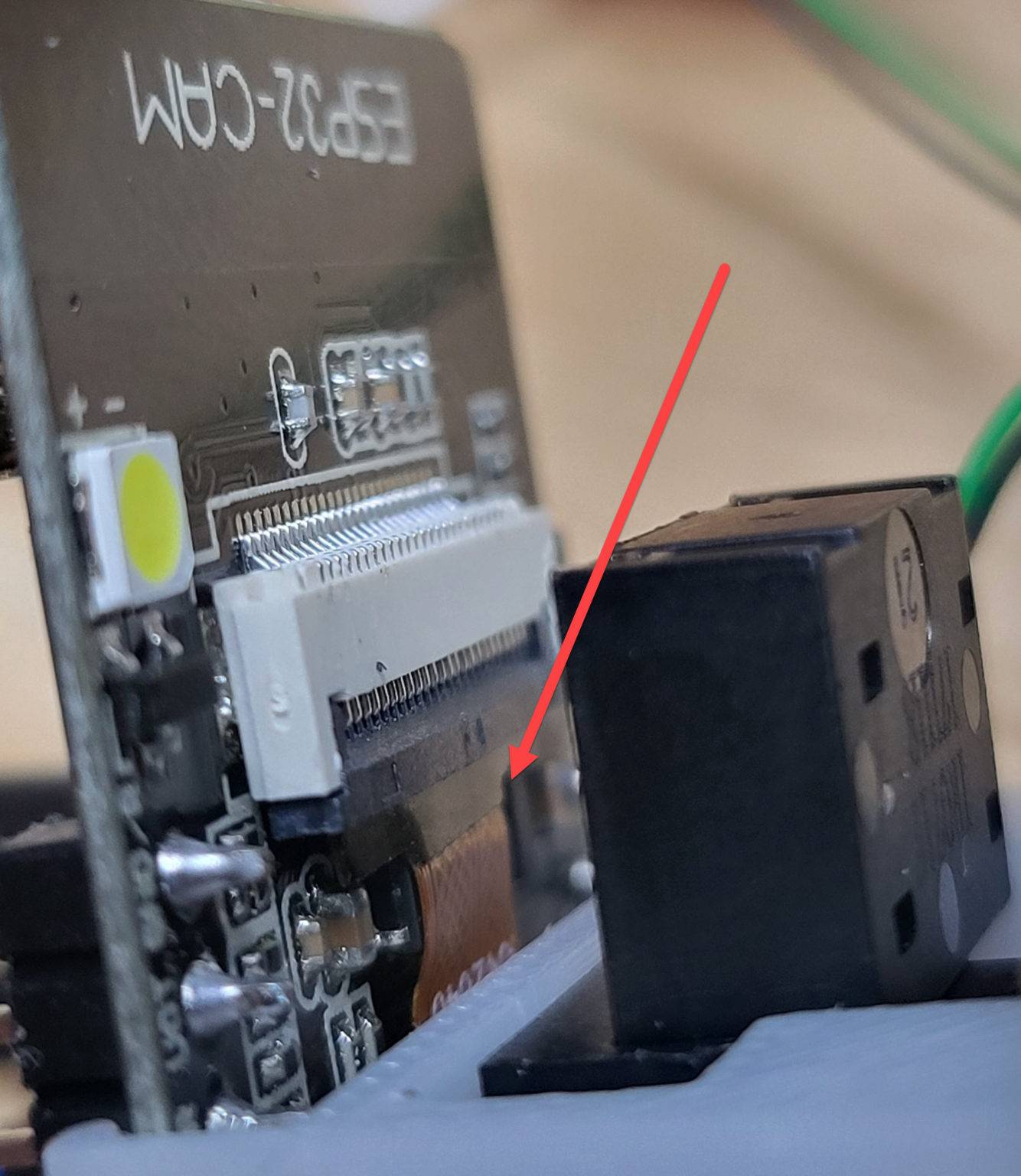
The next part can be a little tricky. You need to slide the ESP32 into the part of ESP32CAM_IR_sensor_holder_V2 behind the OV2640 camera and guide the ribbon cable into the connector. This can be tricky even without the extra parts so take you time. Once aligned finish inserting and lock the cable into place. You may also want to apply a little glue to the ends of the ESP32 and ESP32CAM_IR_sensor_holder_V2 for extra holding strength.
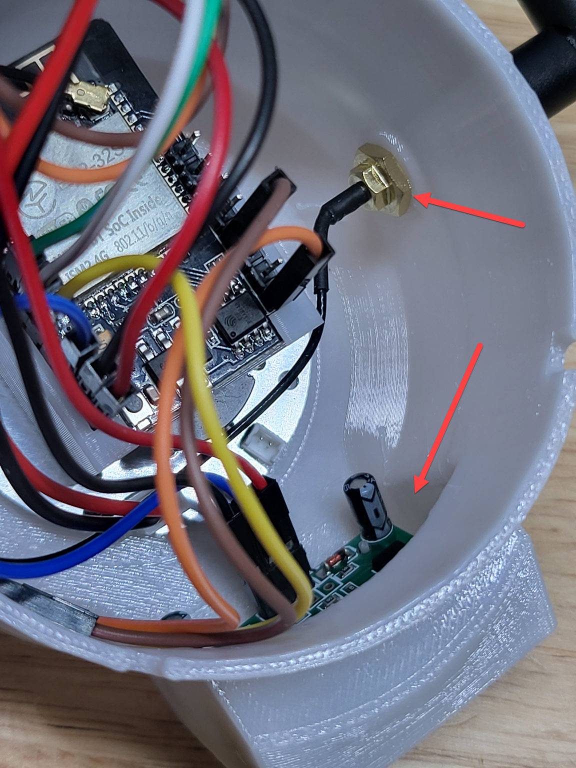
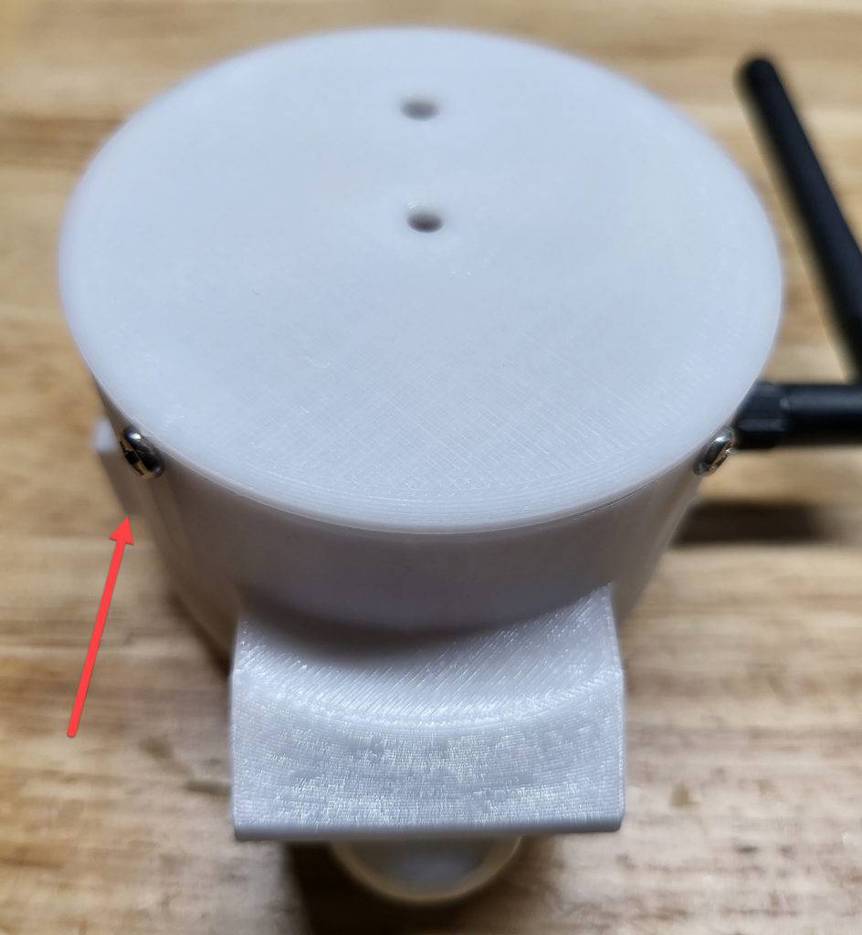
Final assembly can be done in various order but assuming you already have all wires connected, start by inserting the external antenna base into the side hole of ESP32CAM_IR_main_V2_deeper. Attach the washers and nut to hold it in place.
Next drop the HC-SR501 PIR module into the lower portion. You will need to drop a little hot glue to hold it in place.
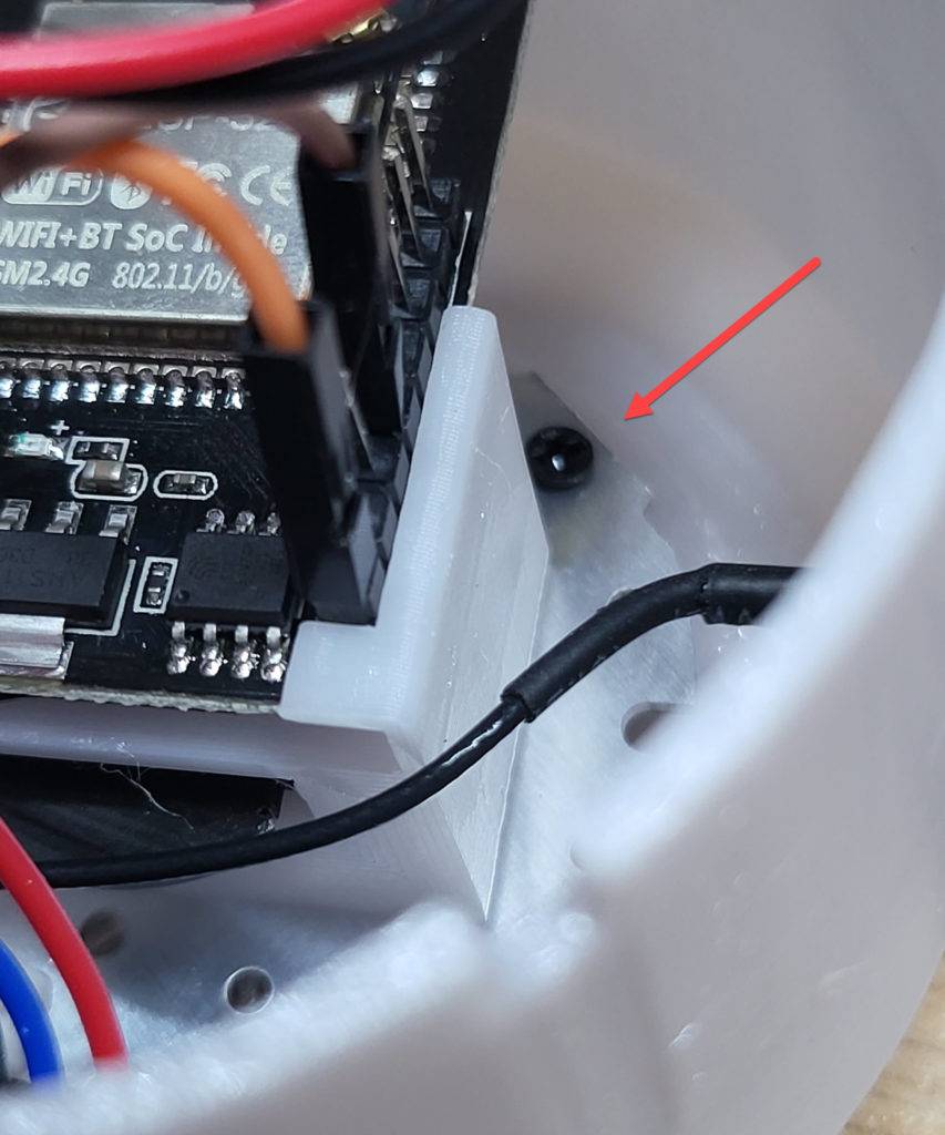
Insert the ESP32-CAM/Lens/LED assembly into ESP32CAM_IR_main_V2_deeper and align the 3 holes. Using 3 M2x6 countersunk self tapping screws, secure the assembly into place.

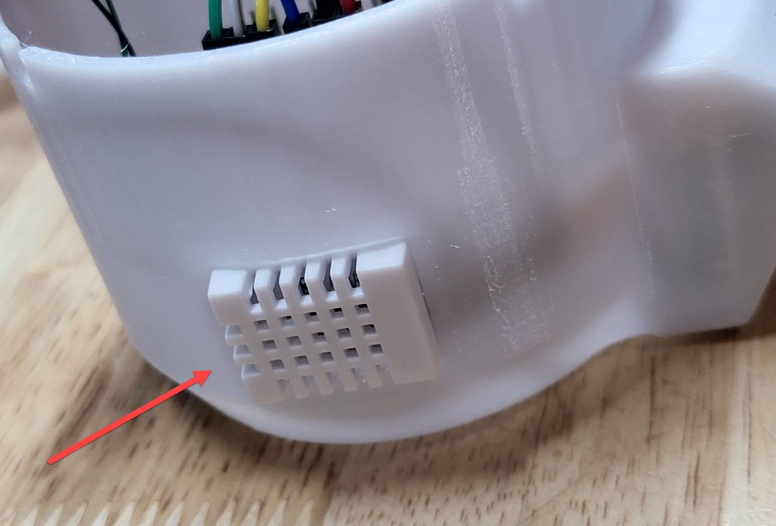
Now place the the DHT22 into the side (rectangle) hole using hot glue to hold in place. Arrange the MP1584EN and MX1508 along the outer sides.
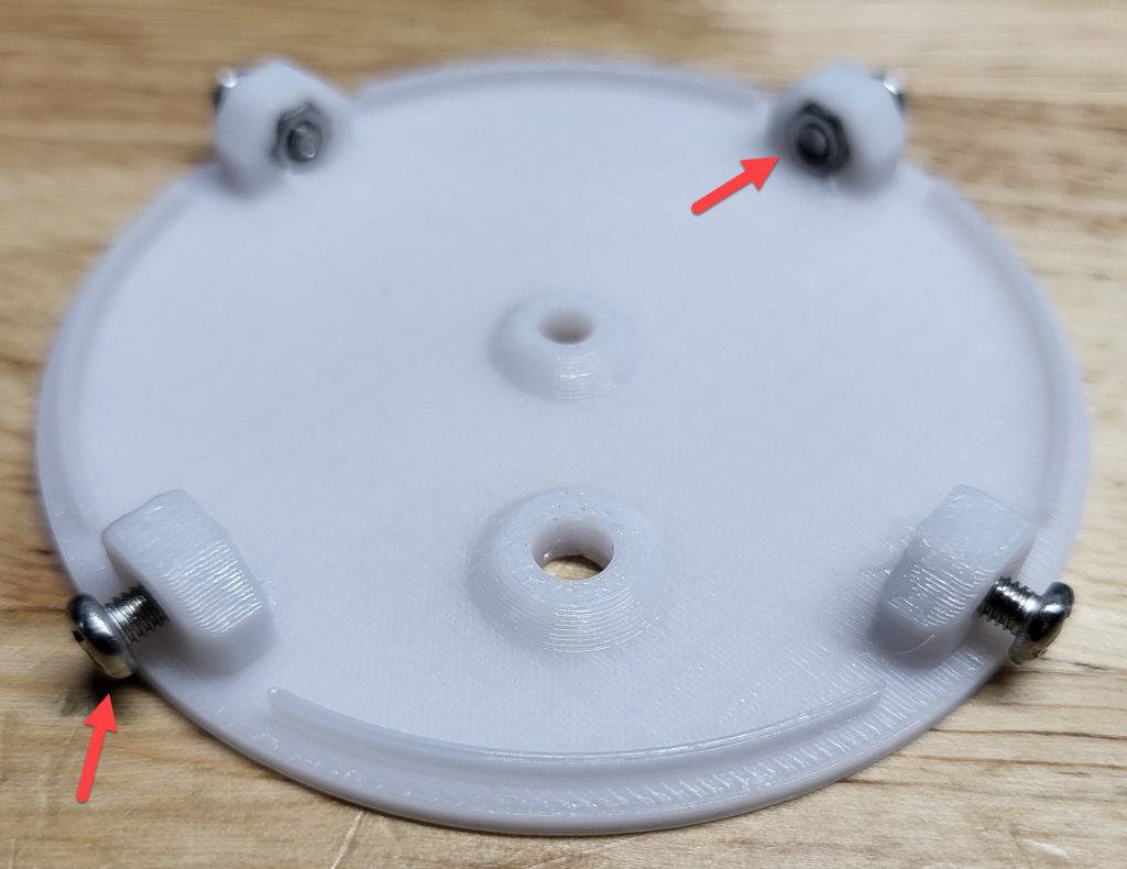
Use the M3x8 pan head machine screws with hex nuts to secure the ESP32CAMT12_cap to ESP32CAM_IR_main_V2_deeper.
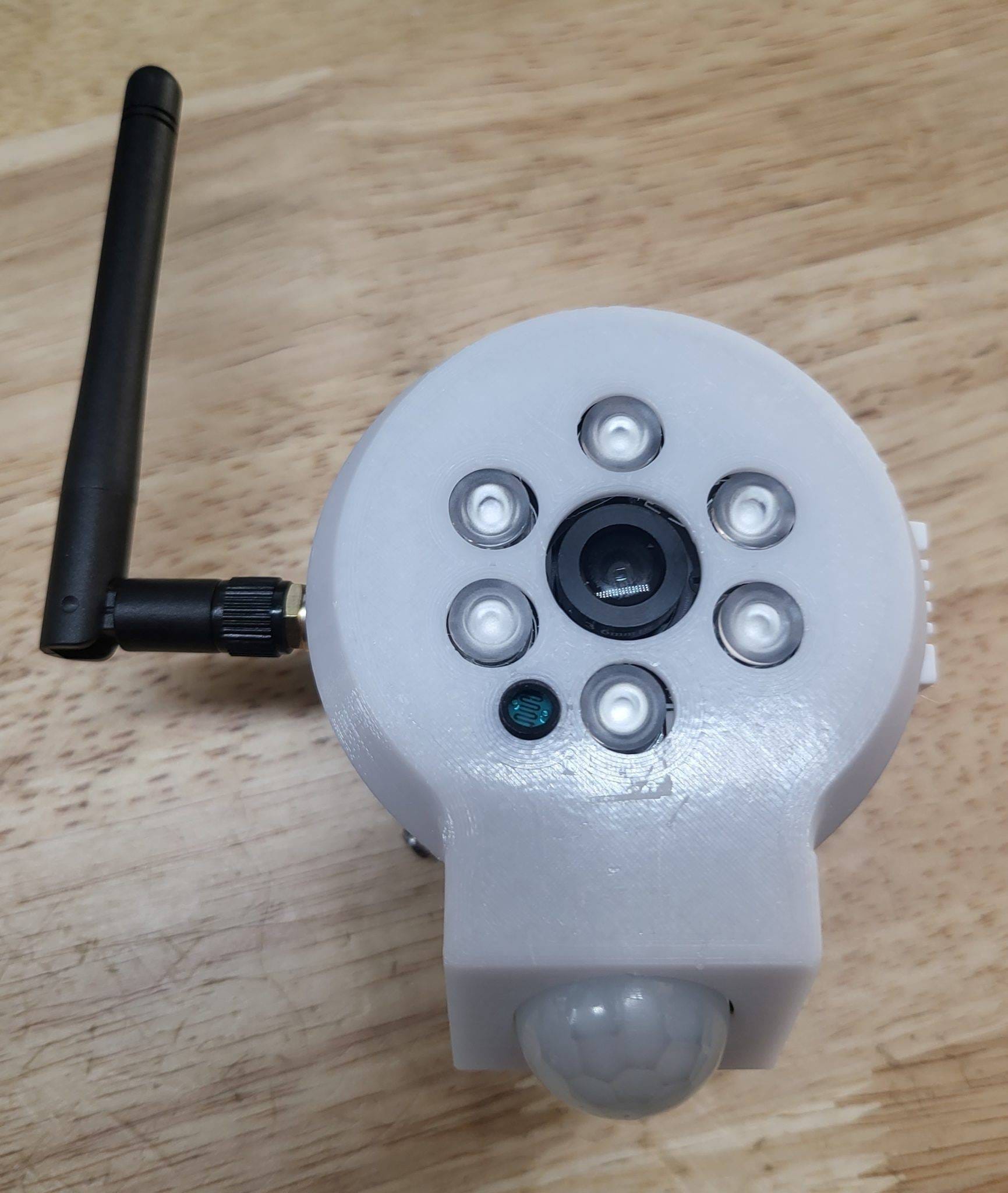
SUCCESS
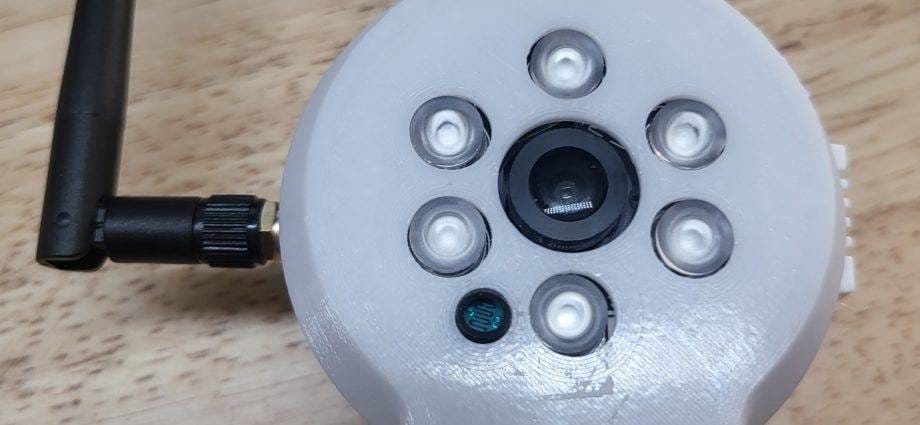
Hopefully your end results looks similar to mine below. Finish setting it up in ESPHome and Home Assistant and enjoy!
Original files created and designed by Hackermagnet (https://hackermagnet.com/night-vision-on-esp32-cam/) and shared under Creative Commons Attribution 4.0 International (CC BY 4.0). My contributions (ESP32CAM_IR_main_V2_deeper.stl, ESP32CAM_IR_sensor_holder_V2_extended.stl and ESP32CAM_IR_sensor_holder_V2_retracted.stl) are shared under Creative Commons Attribution-ShareAlike 3.0 Unported (CC BY-SA 3.0).